Research on the influence of aero-optical effects on starlight atmospheric refraction navigation under supersonic conditions
 Yufeng Yang1,2 and
  Ningning Song1*
- 1Xi'an University of Technology, School of Automation and Information Engineering, Xi'an, China
- 2Shaanxi Civil-Military Collaboration Key Laboratory of Intelligence Coordination Networks, Xi'an University of Technology, Xi'an, China
In the starlight atmospheric refraction navigation when the starlight transmits in the supersonic flow field, the aero-optical effect will reduce the accuracy of navigation. In this paper, the aircraft model is established by ICEM and Fluent is used to simulate the atmosphere density distribution at different altitudes and speeds. Then, the principle of geometric optics is used to track the starlight, the angular deviation of starlight transmission is deduced, and finally, the influence of different speeds and altitudes on starlight atmospheric refraction navigation is analyzed. The results show that the aero-optical effect produced by supersonic vehicles is related to the flight altitude and flight speed. Taking the flight altitude of 20 and 30 km as an example, when the flight speed is Mach 2, the angular deviation caused by the aero-optical effect is 1.045 and 0.699“ respectively, and when the flight speed is Mach 10, the angular deviation is 20.075 and 4.643”, respectively. Therefore, the aero-optical effect can be ignored at the altitude of 30 km and above. However, the influence of the aero-optical effect at 20 km needs to be judged according to the flight speed.
Introduction
The unique technical advantages of starlight atmospheric refractive navigation make it more and more important in the military, the high-precision, low-cost, miniaturized and fully autonomous starlight atmospheric refractive navigation technology has become the future development trend [1–3]. When the aircraft is at supersonic speed, the shock waves, turbulent boundary layer, a shear layer will be formed in the surrounding atmosphere, this complex airflow field will lead to the uneven atmosphere density, which will result in offset, blur, jitter and energy attenuation of the target image in the imaging system. This phenomenon is called the aero-optical effect [4–6]. Under the condition of an optical system with a given aperture, focal length and band, the angle of incidence is 40°, the flight altitude is 10 km and the speed is Mach 3, the half-field of view angle error caused by the image offset is about 6“ [7]. Under the ideal condition, domestic star sensor products can currently achieve an attitude output of better than 10”. In astronomical navigation for aircraft, the influence of aero-optics on star sensors, especially large field star sensors, cannot be ignored.
In the 1970's, the United States began to study aero optics in subsonic and transonic flow fields [8]. By the end of the 20th century, the research of aero-optics in the United States began to turn to hypersonic flow fields and completed the design and construction of a national high-energy shock wind tunnel, which pushed the research of aero optics to a climax. In 2004, Duffin et al. [9] made a detailed analysis of the flow field structure and studied the variation law of the optical path difference with time in the flow field. In 2006, Liu et al. [10] solved the Navier-Stokes (N-S) equation with the finite volume difference method and calculated the optical distortion when a light beam passed through the aircraft outflow field of Mach 0.8. In 2010, Ding-Hua et al. [11] proposed a ray tracing algorithm with variable step size, which could adjust the step size according to the refractive index of the grid and the size of the grid where the ray is located, it could achieve high tracking accuracy and the angular deviation error of tracing could reach about 1%. In 2015, Banakh et al. [12] studied the aero-optical effect caused by the beam passing through the shock layer of the hypersonic vehicle cone. It was found that the flight altitude of the vehicle would weaken the deflection effect of the flow field on the beam. In 2017, Yang and Zhu [13] studied the effect of atmospheric turbulence in the stratosphere on starlight transmission based on geometric optics and statistical optics theory, it is found that starlight will be deflected obviously when it passes through atmospheric turbulence, and the deflection degree is related to the density of the flow field. In 2020, Yang et al. [14] developed an Aero-Optical Simulator for Starlight Transmission (AOSST) of starlight in the boundary layer. Compared with the widely used CFD simulation, this method not only effectively reduces the amount of calculation but also achieves satisfactory accuracy. In 2021, Xing et al. [15] used the large eddy simulation model to evaluate the aero-optical effect of the mixed layer with different velocity ratios and concluded that the aero-optical effect of the mixed layer with a low-velocity ratio was more serious. To sum up, in terms of aero-optics, a large number of domestic and foreign scholars have mainly focused on its influence on starlight transmission at low Mach numbers and low altitudes, while there are fewer studies on the impact of high Mach numbers, high altitudes and their variation range on the starlight atmospheric refraction navigation.
In this paper, the external flow field model of hypersonic aircraft is firstly established, the starlight is traced by the ray tracing method, the deflection angle of each ray is calculated, and the offset of starlight transmission is comprehensively analyzed. Finally, the influence of light offset on starlight atmospheric refraction navigation is studied, which provides theoretical guidance for improving the accuracy of starlight atmospheric refraction navigation of hypersonic vehicles.
Starlight transmission under hypersonic conditions
External flow field model of hypersonic vehicle
In the case of hypersonic, the interaction between the incoming flow and the aircraft produces a non-uniform flow field, which causes the aero-optical effect, as shown in Figure 1. When starlight transmits in a non-uniform medium, the transmission path will change with the change of the refractive index in the flow field, and the refractive index of the flow field is mainly determined by the density of the flow field outside the aircraft.
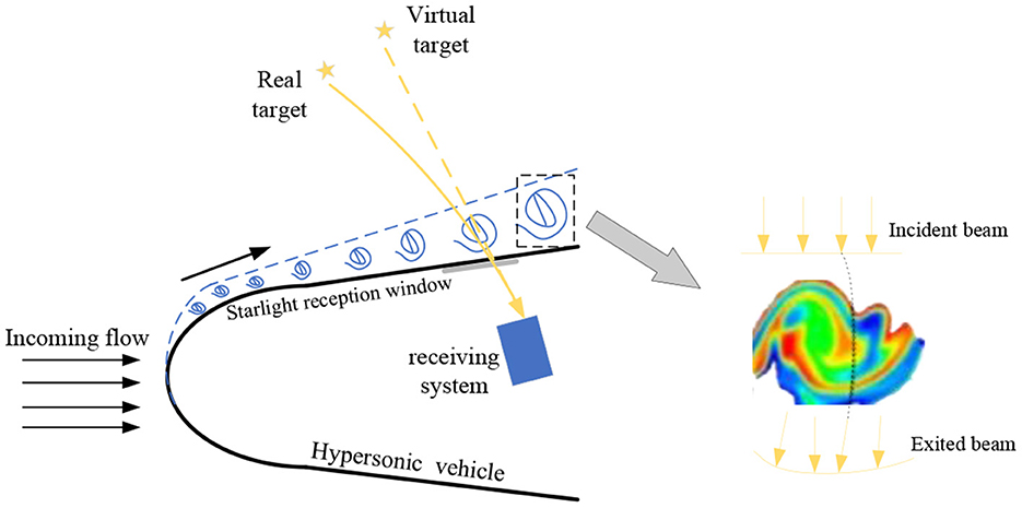
Figure 1. Schematic diagram of the influence of aero optical effects on starlight atmospheric refraction navigation.
Governing equation
The high-speed flow field around the aircraft satisfies the N-S equation, in a three-dimensional Cartesian coordinate system, the conservative differential form of N-S equations for compressible viscous fluids is:
where FU‵GU and HU are inviscid convective vector fluxes; FV‵GV and HV are viscous vector fluxes. The specific expression can be found in Ref. 15.
Because the N-S equation is not closed. Therefore, four thermodynamic equations need to be introduced:
where ρ is the density; e is the total energy per unit mass of gas; μ is the dynamic viscosity coefficient; k is the thermal conductivity. In addition, R is the gas constant; γ is the specific heat coefficient of gas, which is generally γ= 1.4; Coefficient C1 = 1.458×10⁻⁶kg·m−1·s−1·K−1/2; C2 = 110.4 K, Pr is the Prandtl number, for complete gas, Pr = 0.72 is usually used.
Turbulence model
Adopt standard k-ε the model simulates the hypersonic turbulent flow field, in the standard k- ε model, By solving the k equation of turbulent flow energy and turbulent dissipation rate ε equation, then k and ε to calculate turbulent viscosity μt. Finally, the solution of Reynolds stress is obtained by the Boussinesq hypothesis. The corresponding equation and function expression are [16, 17]:
Where: Model coefficient Cμ = 0.09, Cε1 = 1.44, Cε2 = 1.92, σk = 1, σε = 1.3.
Starlight transmission model
The theory of light transmission can be visually described by Fermat's principle, which states that the path with the shortest time required for light to pass through is the only transmission path, that is, the path of light (Optical Path Length, OPL). The optical path is the product of the refractive index n of the medium and the actual path of the light. If the refractive index changes with the spatial position, the optical path of the light transmitted from a to b can be expressed by the path integral of the refractive index:
where n is the refractive index and equation (9) satisfies Fermat's principle .
It can be seen from formula [9] that in a non-uniform flow field, due to the change of refractive index, the transmission path of light should be a curve. In order to find the precise transmission path of light in a non-uniform medium, the basic equation of light transmission in a non-uniform field can generally be derived by using the Sine Refraction Law. The non-uniform medium is continuously layered in the transmission direction and the refractive index shows a gradient distribution, the light travels straight through the interior of the grid, refracting at the boundaries of two adjacent grids.
Suppose that a ray passes through the flow field region of grid 1 at the incident angle θ0 from (x1, y1), reaches the flow field region of grid 2, and it is refracted at the adjacent boundary of the two grids. According to the law of refraction, the relationship between the refraction angle θ1 and the incidence angle θ0 can be expressed as:
When the refractive index changes continuously, the light transmission path will become curved, ds is a small arc length on the propagation path, then(ds)2 = (dx)2 + (dy)2,dx/ds = sinθ can be simplified to:
The above equation is the path of light propagation. If x is differentiated, the light propagation equation can be simplified to a partial differential equation as:
Equation [13] is the basic equation for the transmission of light, for a uniform medium the refractive index n(y) is constant, equation [13] is equal to 0, indicating that light travels in a straight line, while in non-uniform media, gradient change of the refractive index results in a curvilinear transmission of light, and the relationship between refractive index and density can refer to Gladstone-Dale's law of refractive index [16]:
Where KGD is the conversion coefficient between density and refractive index, referred to as the G-D coefficient in cm3/g; ρ is the flow field density, where the G-D coefficient of the standard atmosphere is expressed as:
With the ray-tracing method, the total Optical Path of the Light (OPL) passing through the outflow field of the aircraft to the receiving window can be get and compared with OPLref, and the Optical Path Difference (OPD) can be also calculated:
Suppose the light is incident at a certain angle θ0 and passes through the flow field, finally leaves the flow field at an exit angle θn, where the difference between the exit angle θn and the incident angle θ0 is called the angular deviation, which is expressed by Δθ:
Navigation system model
Extended Kalman Filter (EKF) is used in navigation system model, which is one of the most commonly used optimal estimation algorithms in the design of aircraft navigation systems. The principle is to linearize the non-linear model on the basis of Kalman filter, and then perform the optimal estimation.
System state model
When establishing the system model, only the influence of the gravity of the earth's mass center and the second-order harmonic term perturbed by the gravitational field is considered, while other perturbation factors are usually equivalent to Gaussian white noise. The system state equation is as follows:
In equations (18), (x, y, z) and (vx, vy, vz) are the position and speed of the aircraft, respectively, μ is the gravitational constant, J2 is the gravitational coefficient and Re is the radius of the earth; (ΔFx,ΔFy,ΔFz) are the effects of higher-order perturbation terms of the earth's aspherical perturbation, sun and moon perturbations, solar light pressure perturbations and atmospheric perturbations.
Measurement model with refraction angle θ as the observed quantity
where rs is the vehicle position vector, s is the directional unit vector of the star, u is the directional unit vector of the starlight observed by the star sensor and u is the unit vector in the plane which s and rs lies, and is perpendicular to the vector s.
By the geometric relationships it is known that:
where hg is the tangent altitude of starlight, ha is the apparent altitude of starlight, re is the radius of the earth.
From the refraction law of light, it can be deduced that the relationship between the tangent altitude hg and the apparent altitude ha is:
Where hs is the atmospheric elevation. From Equations (19) to (22) it can be known that:
Denote the observation error as Z, then the observation model is:
where is the measurement error array, which is assumed to be white Gaussian noise with zero mean.
Analysis of simulation results
Simulation results of flow field in different states
The influence of aircraft altitude on the external flow field
It can be seen from Figures 2a–d that due to the fast flight speed, the strong impact will cause severe compression of the surrounding atmosphere, and the aircraft will rub with the atmosphere, resulting in a significant shock layer at the head of the aircraft.
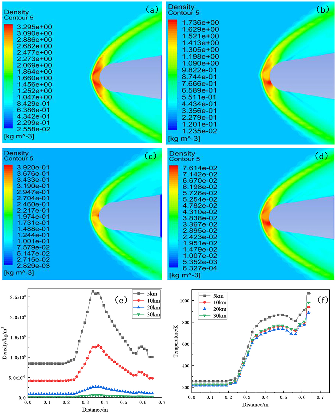
Figure 2. Comparison of density distribution of hypersonic vehicle disturbed flow field at different altitudes. (a) 5 km; (b) 10 km; (c) 20 km, and (d) 30 km. Distribution of density and temperature at different flight altitudes (5, 10, 20, 30 km) at a flight speed of Mach 5. (f) density trend and (e) temperature trend.
The density distribution cloud maps of XOY section of atmospheric disturbance flow field at different flight altitudes are compared, it can be found that the distribution around the aircraft body has changed drastically, and the most obvious parts of the change are concentrated in the shock layer area at the head of the aircraft, and the flow field is symmetrical up and down, because the starlight is above the aircraft, so only the upper side of the flow field is analyzed. The density distribution range of atmospheric disturbance flow fields at flight altitudes of 5, 10, 20, and 30 km is, respectively 2.55 × 10⁻²-3.29 kg/m3, 1.23 × 10⁻²-1.73 kg/m3, 2.82 × 10⁻³-3.92 × 10⁻¹ kg/m3, and 6.32 × 10⁻⁴-7.61 × 10⁻² kg/m3, respectively. With the increase of flight altitude, the perturbed flow field decreases, this is because the atmosphere becomes thinner and thinner with the increase of altitude. Therefore, the temperature, pressure, density and other parameters of the atmosphere itself will also reduce. At the same time, the thin atmosphere will directly reduce the compression degree of the atmosphere at the head of the aircraft, which causes the high-temperature gas effect of the aircraft on the surrounding atmospheric molecules weakening, resulting in a decrease in the density of the disturbed flow field.
The density and temperature of the disturbed flow field change with the distance to the aircraft surface at different altitudes is shown in Figures 2e,f, it can be found that the density passing through the shock layer will jump, as the lower the flight altitude, the greater the peak. When the flight altitude is 30 km, the flow field density of the aircraft hardly changes, which means the influence of the aero-optical effect is small. For the influence of temperature, as shown in Figure 4F, it can be seen that the closer to the receiving window, the higher the temperature, but the flight altitude has no obvious effect on the temperature change. This is because the standard atmospheric temperature ranges from 210 to 290 k with altitude and the effect is not obvious near the aircraft.
The effect of the flying Mach number on the outflow field of the aircraft
As shown in Figures 3a–h, it can be seen the maximum value of density distribution at the flight speed of Mach 10 compared to Mach 5 increases by 1.14, 0.55, 0.16, and 0.02 kg/m3, respectively. With the increase of aircraft Mach number, the greater the peak of density, the smaller the atmospheric disturbance distance and the closer the flow field is to the surface of aircraft. For the distribution of temperature, it can be seen that the higher the Mach number, the higher the temperature. By comparing parameters above, it can be found that when the flight altitude remains unchanged, the basic parameter values of the disturbed flow field increase with the increase of the flight Mach number, this is mainly because with the increase of flight speed, the compression degree of the aircraft body to the surrounding atmosphere increases significantly, the high temperature gas effect between the aircraft and the surrounding atmospheric molecules is significantly enhanced, which causes the density and temperature of the disturbed flow field to increase.
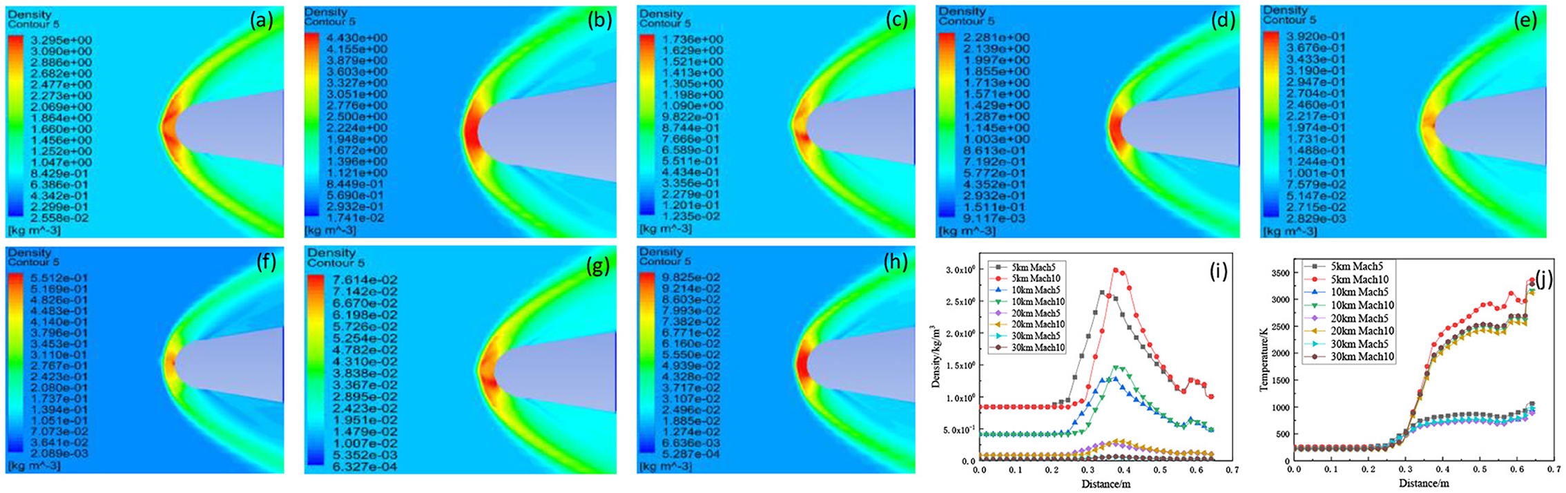
Figure 3. Comparison of density distribution of disturbed flow field of hypersonic vehicle at different flight speeds and altitudes (a) Flight altitude 5 km flight speed Mach 5. (b) Flight altitude 5 km flight speed Mach 10. (c) Flight altitude 10 km flight speed Mach 5. (d) Flight altitude 10 km flight speed Mach 10. (e) Flight altitude 20 km flight speed Mach 5. (f) Flight altitude 20 km flight speed Mach 10. (g) Flight altitude 30 km flight speed Mach 5. (h) Flight altitude 30 km flight speed Mach 10; Distribution law of disturbed flow field and temperature of hypersonic vehicle at different flight Mach numbers (i) density distribution and (j) temperature distribution.
Simulation and analysis of starlight transmission
Refractive index distribution of atmospheric disturbance
The density and temperature distribution of the atmospheric disturbance flow field under different conditions can be obtained by calculation. The refractive index distribution of the atmospheric disturbance flow field can be calculated according to Formula [14], the refractive index n distribution of the atmospheric disturbance flow field with a typical wavelength of 550 nm can be obtained, as shown in Figure 4A.
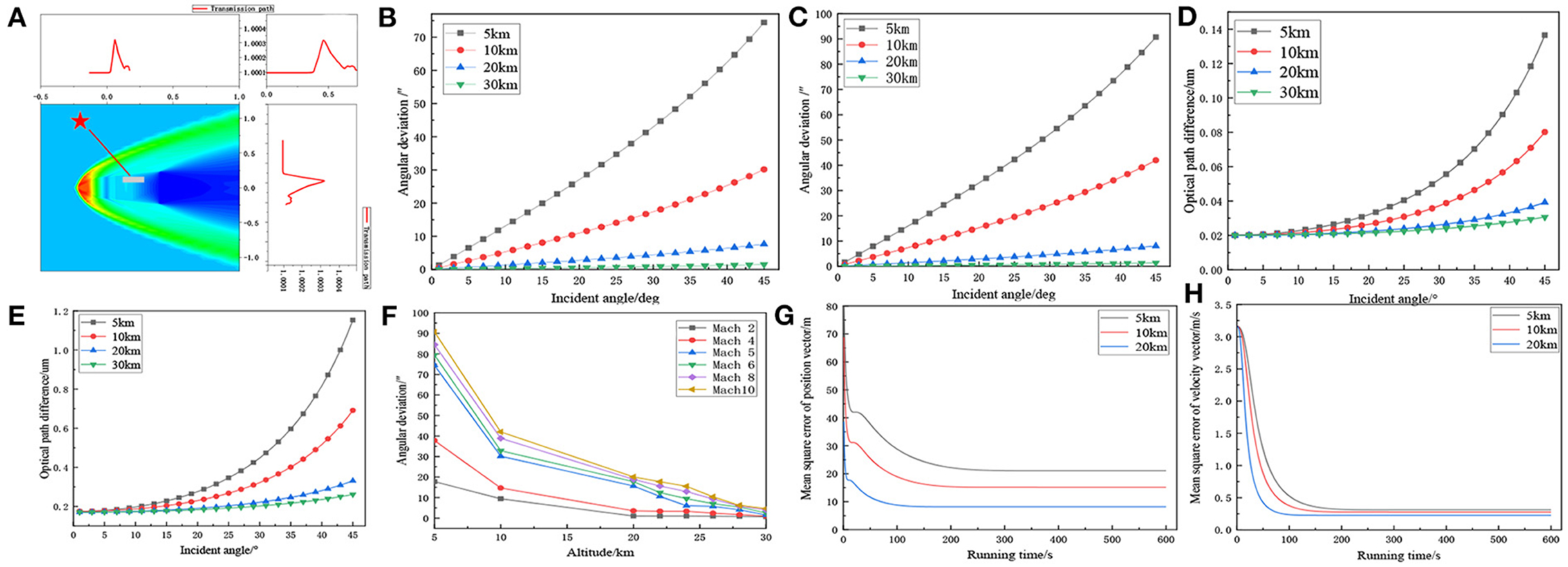
Figure 4. (A) Refractive index distribution at flight altitude of 10 km and flight speed of Mach 5. Variation curve of angular deviation with incident angle of light (B) flight speed Mach 5 and (C) flight speed Mach 10. Curve of optical path difference with incident angle of light (D) flight speed Mach 5 and (E) flight speed Mach 10. (F) Relationship between deflection angle and Mach number when the incident angle is 45 degrees and the altitudes are 5, 10, 20, and 30 km, respectively; EKF filtered navigation error. (G) mean square error of position vector and (H) mean square error of velocity vector, respectively.
Angular deviation and optical path difference
With the increases of the light incident angle, when the light arrive at the receiving window, the angular deviation and the optical path difference will increase, and the aero-optical effect will enhance significantly, as shown in Figures 4B–E. According to the propagation process of the light in the grid, the larger the incident angle of the light, the larger the refraction angle of the light, the refraction angle is used as a new incident angle for the next propagation. As the angle increases, the angular deviation also increases, making the light more and more deviated from the original transmission path, so the transmission path becomes longer and the transmission angle becomes larger.
As shown in Figure 4F, when the incident light is 45°, the flight speed is Mach 5, and the angular deviation is 74.42, 30.15, 15.64, and 1.50“ respectively at the flight altitude 5, 10, 20, and 30 km, From the simulation data, it can be seen that the deflection angle decreases with the increase of flight altitude, and increases with the increase of Mach number, it is because the altitude and flight speed are the main factor affecting the flow field density of the aircraft. The decrease of altitude or the increase of flight speed will increase the flow field density and lead to the increase of deflection angle.
Therefore, taking the micro star sensor [17] with measurement accuracy of about 5.5 “as an example, when the flight speed is Mach 2, the angular offset caused by the aero-optical effect at flight altitudes of 20 and 30 km is 1.045 and 0.699″ respectively; when the flight speed is Mach 10, the angular offset caused by the aero-optical effect at flight altitude of 20 and 30 km is 20.075 and 4.643″, respectively. In summary, the aero-optical effects of hypersonic vehicles are related to both flight altitude and flight speed. When the altitude of vehicle is 30 km and above, the aero-optical effect can be ignored, but when the flight altitude is 20 km, it is necessary to judge whether the influence of aero-optical effect can be ignored according to the flight speed.
As shown in Figures 4G,H, when the sampling period is 1 s, the mean square errors of the position vector of the aircraft at the flight altitude of 5, 10, and 20 km are 21.06, 15.15, and 8.17 m, respectively, and the mean square error of the speed vector is 0.31, 0.27, and 0.22 m/s, respectively. From the calculation results, it can be seen that the aero-optical effect has a certain influence on the navigation accuracy of starlight atmospheric refraction. Since the traditional Kalman Filter can only be applied to linear systems, the estimation accuracy is reduced, so the EKF filtering algorithm is stable and convergent.
Conclusion
In this paper, the influence of aero-optical effect on stellar atmospheric refraction navigation is studied at hypersonic condition. The principle of geometric optics is used to trace the starlight, the measurement equation with refraction angle as the observation model is established, and the influence of the aero-optical effect on navigation accuracy is analyzed by Extended Kalman Filter. The results show that: The intensity of aero optical effect is affected by the flight altitude and speed of hypersonic vehicle, according to the measurement accuracy of the star sensor, when the altitude of aircraft is 30 km and above, the aero-optical effect can be ignored, but the impact of aero-optical effects at 20 km needs to be judged according to the flight speed; In addition, with the flight altitude and Mach number increase, it will increase the angular offset, thus affecting the navigation accuracy of starlight atmospheric refraction. In summary, aero-optical effects can affect starlight atmospheric refraction navigation accuracy cannot be ignored. Starlight atmospheric refraction navigation has a high navigation accuracy and is suitable for the autonomous navigation research and application of near-Earth aircraft.
Data availability statement
The original contributions presented in the study are included in the article/supplementary material, further inquiries can be directed to the corresponding author/s.
Author contributions
NS wrote the first draft of the manuscript. YY contributed to editing. All authors contributed to the article and approved the submitted version.
Acknowledgments
The authors are grateful to the reviewers and editors for their input and constructive comments.
Conflict of interest
The authors declare that the research was conducted in the absence of any commercial or financial relationships that could be construed as a potential conflict of interest.
Publisher's note
All claims expressed in this article are solely those of the authors and do not necessarily represent those of their affiliated organizations, or those of the publisher, the editors and the reviewers. Any product that may be evaluated in this article, or claim that may be made by its manufacturer, is not guaranteed or endorsed by the publisher.
References
1. Hartman DW, Dzanic T, Witherden F, Tropina A, Miles RB. Numerical analysis and prediction of aero-optical effects. AIAA Scitech 2021 Forum. (2021) 3:335. doi: 10.2514/6.2021-0335
2. Xiaolin N, Longhua W, Xinbei B, Jiancheng F. A scheme design of a starlight refraction satellite autonomous navigation system. J Astronaut. (2012) 33:1601–10. doi: 10.3873/j.issn.10001328.2012.11.007
3. Qian HM, Sun L, Cai JN, Huang W. A starlight refraction scheme with single star sensor used in autonomous satellite navigation system. Acta Astronautica. (2014) 96:45–52. doi: 10.1016/j.actaastro.2013.11.028
4. Hui W, Chen S, Zhang W, Dang F, Ju L, Xu X, et al. Evaluating imaging quality of optical dome affected by aero-optical transmission effect and aero-thermal radiation effect. Optics Express. (2020) 28:20. doi: 10.1364/OE.373020
5. Wyckham C, Smits A. Comparison of Aero-Optic Distortion in Hypersonic and Transonic, Turbulent Boundary Layers with Gas Injection. 37th AIAA Plasmadynamics and Lasers Conference. San Francisco, CA (2006). doi: 10.2514/6.2006-3067
6. Lin W, Jiancheng F, Zhaohua Y. Study on aero-optical distortion simulation of high refraction index gradient regions in hypersonic turbulent flow. Acta Optica Sinica. (2009) 29:2952–7. doi: 10.3788/AOS20092911.2952
7. Yang W, Cai C, Ding M, Zhou C. Analysis of aero-optical effects of turbulence flow field of supersonic/hypersonic vehicle. Opto-Elect Engin. (2009) 36:1.
8. Tian L. Mechanistic Study on the Fine Structure of the Flow Field of the Supersonic Optical Cowl and Its Aerodynamic-Optical Effect. Changsha: National University of Defense Technology (2011).
9. Duffin D, Gordeyev S, Jumper E. Visualizing Index-Of-Refraction Variations in Optically Active Flow Field. 11th International Symposium on Flow Visualization, Indiana, USA. August 9–12. (2004).
10. Liu J, Li S, Jin G, Liu S, Zhang X. Influence on laser propagation of aero-craft's outer fluid field. Acta Photonica Sinica. (2006) 04:599–602. doi: 10.1677/jme.1.02008
11. Ding-Hua F, Sha P, Zheng-Yu T, Hua L. Ray tracing method with exciting flow field. J Nat Univ Defense Technol. (2010) 32:6–10. doi: 10.3969/j.issn.1001-2486.2010.01.002
12. Banakh V, Sukharev A, Falits AV. Optical beam distortions induced by a shock wave. Appl Optics. (2015) 54:23. doi: 10.1364/AO.54.002023
13. Yang B, Zhu XY. Influence of atmospheric turbulence on starlight transmission during satellite celestial navigation in stratosphere. Yuhang Xuebao J Astronaut. (2017) 38:359–66. doi: 10.3873/j.issn.1000-1328.2017.04.005
14. Yang Bo, Fan Z, He YU. Aero-optical effects simulation technique for starlight transmission in boundary layer under high-speed conditions. Chin J Aeronaut. (2020) 33:13. doi: 10.1016/j.cja.2020.02.015
15. Xing B, Cai B, Yang B, Zhang B. Study on the aero-optical effect of supersonic mixing layer with different velocity ratio. Flight Cont Detect. (2021) 4:51–7. Available online at: https://xueshu.baidu.com/usercenter/paper/show?paperid=1s5p0ex0xp1h0tu02f1m00j0s9664555&site=xueshu_se&hitarticle=1
Keywords: aero-optical effect, starlight atmospheric refraction navigation, supersonic vehicles, geometric optics, ray tracing
Citation: Yang Y and Song N (2022) Research on the influence of aero-optical effects on starlight atmospheric refraction navigation under supersonic conditions. Front. Appl. Math. Stat. 8:1081286. doi: 10.3389/fams.2022.1081286
Received: 27 October 2022; Accepted: 25 November 2022;
Published: 08 December 2022.
Edited by:
Heng Liu, Guangxi University for Nationalities, ChinaReviewed by:
Bo Wang, Qilu University of Technology, ChinaWei Xiang, Huainan Normal University, China
Copyright © 2022 Yang and Song. This is an open-access article distributed under the terms of the Creative Commons Attribution License (CC BY). The use, distribution or reproduction in other forums is permitted, provided the original author(s) and the copyright owner(s) are credited and that the original publication in this journal is cited, in accordance with accepted academic practice. No use, distribution or reproduction is permitted which does not comply with these terms.
*Correspondence: Ningning Song, 2200321154@stu.xaut.edu.cn