Mechanical model of the over-stroke displacement behaviour for double concave surface slider anti-seismic devices
 Antonio Di Cesare
 Felice Carlo Ponzo
 Alessio Telesca
- School of Engineering, University of Basilicata, Potenza, Italy
For double concave curved surface slider (DCCSS) isolators with a flat rim and lacking restrainers, such as those most commonly used in Europe, the rigid slider can exceed the geometrical capability of the housing plate during earthquakes stronger than those produced in simulations. During this over-stroke displacement, DCCSSs preserve the ability to support superstructure gravity loads and the capacity to dissipate energy. There are currently no applicable hysteresis rules or available algebraic solutions that can be used to predict over-stroke behaviour for response-history analysis. This study presents an algebraic solution to extend basic theories for estimating the actual limit displacement of DCCSS devices with over-stroke capacity. DCCSS behaviour in the over-stroke sliding regime was modelled with a focus on geometrical compatibility and kinematics. The proposed analytical formulation was calibrated on the basis of experimental controlled-displacement tests performed on single DCCSS devices. A case study of a six-storey reinforced concrete frame isolated building was modelled using a combination of non-linear elements that are currently available in several structural analysis software packages and able to correctly model over-stroke displacement behaviour for non-linear time history analyses. The DCCSS model was augmented with a friction model capable of accounting for torsional effects, axial load, and velocity variabilities. Comparison with non-linear dynamic analysis outcomes shows that the forces and displacements in the over-stroke sliding regime are predictable and therefore useful for the designer.
1 Introduction
Isolation devices are designed to uncouple the movement of the structure from the underlying ground, and this attribute is granted by their low horizontal stiffness. The most commonly used isolation devices are elastomeric and sliding bearings, such as curved surface sliders (CSSs) (Zayas et al., 1987), which are being increasingly used in the seismic isolation systems of buildings and bridges.
Double concave curved surface slider (DCCSS) isolation bearings consist of two facing concave stainless-steel surfaces separated by an inner rigid slider characterized by
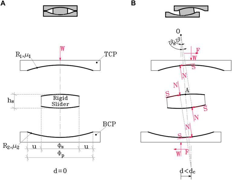
FIGURE 1. Exploded cross-section of the DCCSS bearing. in static conditions (A) and in the sliding regime (B) (Sarlis and Constantinou 2013).
Previous studies have proposed a variety of numerical modelling and experimental tests for slider isolators (Constantinou et al., 1990; Almazán and De La LLera 1998, 2011; Fenz and Constantinou 2006; Fenz and Constantinou 2008a; 2008b; Becker and Mahin 2012a; 2012b; Lomiento et al., 2013; Sarlis and Constantinou 2016; Ponzo et al., 2017, 2019, 2020, 2021; De Domenico et al., 2018, 2019; Pavese et al., 2018; Di Cesare et al., 2019, 2021; Pigouni et al., 2019; Quaglini et al., 2012, 2019; Furinghetti et al., 2020) that also involve geometrical compatibility and multibody kinematics formulations (Belfiore et al., 2000; Shabana 2001; Tsai et al., 2005; Popov 2010; Mazza et al., 2017; Nikravesh 2018; Bianco et al., 2020, 2021). Additionally, the behaviour of single and multiple concave surface sliding bearings has been analytically characterized by Sarlis Constantinou (2013).
The analytical description of the DCCSS bearings characterized by the same radii of curvature
Imposing the constraint of TCP being horizontal during motion, the angles can be represented as:
The resultant force
From Eq. 4 and (3the) value of angle
Substituting Eq. 5 into Eq. 4 results in the following:
Considering that the displacement of the TCP is given by
Further details about this equation can be found in Sarlis and Constantinou (2013, Sarlis and Constantinou (2016).
During ground motions with intensities higher than those in simulations, the rigid slider in DCCSSs with flat rims and lacking elements can shift beyond the geometrical capacity of the housing plates in the so-called over-stroke regime (see Figure 2). Over-stroke displacement capacity is a crucial element that can reduce the annual frequency of the collapse displacement being exceed and improve the seismic resilience of a structure that is isolated with these bearings (Di Cesare et al., 2021). However, the mechanical description of this phenomenon has yet to be explored. This paper focuses on the development of an analytical model, based on fundamental mechanical principles, to describe the over-stroke behaviour of DCCSS devices and define their actual limit displacement.

FIGURE 2. Perspective view of the DCCSS in the static condition and in the over-stroke regime.
Following a report by Bao et al. (2017), the envisioned mode of behaviour in the over-stroke regime and the corresponding multi-body kinematic were calibrated in ad hoc experimental tests conducted on devices pushing the horizontal displacement beyond geometrical capability, revealing how the displacement limit better preserves the ability to support vertical loads (Furinghetti et al., 2021a; Di Cesare et al., 2021). The objective of this was to propose an easy tool for predicting limit displacement and the corresponding shear force, starting from the geometrical and mechanical characteristics of the devices.
The proposed formulation was applied in a case study of a six-storey RC-frame-isolated building. A multi-degree of freedom (MDoF) model was implemented for non-linear dynamic analyses that considered three sets of 20 horizontal earthquakes characterized by intensity values around the collapse limit state (CLS) design spectrum. The comparison between the non-linear numerical results accounting for the friction dependencies from variability in the dynamic condition of velocity and axial load, and the proposed algebraic solution defined in the static condition, accurately predicted of over-stroke force and displacement.
2 Mechanical model of over-stroke displacement
In the case of DCCSS bearings with a flat rim without restraining elements, the limit displacement
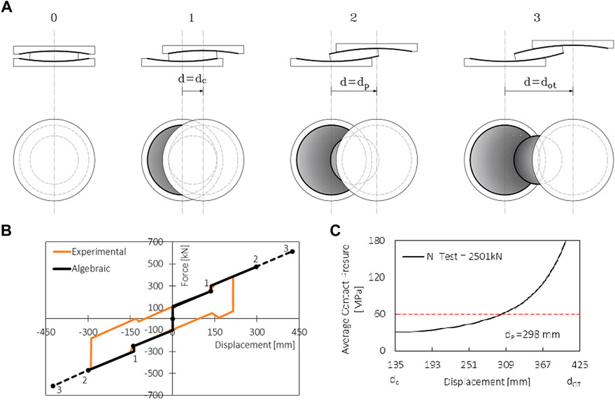
FIGURE 3. (A) Cross-sections and planar views of the DCCSS test specimen (Di Cesare et al., 2019) in three main deformed stages. (B,C) Test diagrams of force (B) and average contact pressure vs. displacement (C).
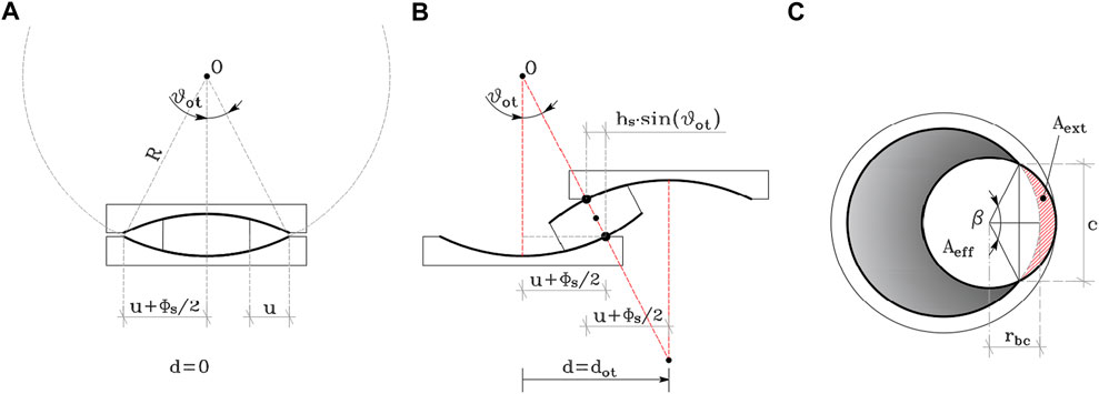
FIGURE 4. Cross-section of the DCCSS in: (A) static conditions (A) and the over-stroke regime (B). (C) Planar view of the rigid slider and the housing plate in the over-stroke regime.
The assumptions of this study were that the bottom and top concave plates are characterized by the same radii of curvature and the same coefficients of friction (
-within the geometric capacity (Regime I):
-in the over-stroke condition (Regime II):
The maximum shear force developed by the device and transferred from the superstructure to the foundation was defined as force
Controlled displacement tests on DCCSS bearings were performed to investigate the actual response of the device when the sliding displacement exceeds the displacement capacity and runs over the sliding surfaces (Di Cesare et al., 2019; Ponzo et al., 2020). The main characteristics of the DCCSS specimen and the experimental testing results are summarized in Table 1 (Di Cesare et al., 2021). The testing protocol consisted of one cycle at constant velocity
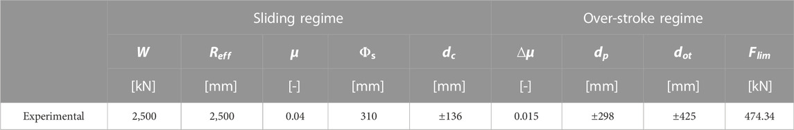
TABLE 1. Main characteristics of the DCCSS specimen and the over-stroke experimental test.
Experimental results showed that when the rigid slider overcomes the concave sliding surface edge (position 1, Figure 3A), it can move up to half of its diameter (position 3, Figure 3A), resulting in a slight increase in force (black line in Figure 3B). In the loading and unloading phases of the first cycle, DCCSS over-stroke behaviour was characterized by a ‘sloping dog bone’ shape, preserving re-centring capability and the ability to support the gravity load. A sudden increase in horizontal force and local equivalent stiffness occured as the sliding pad travelled beyond the housing plate edge (Figure 3C). From a mechanics point of view, this behaviour may have occurred due to an increase in the friction coefficient
In the over-stroke stage of motion (Regime II), the previously exposed Eq. 7 could be properly modified to take an increased friction coefficient
Theoretically, in the over-stroke regime, the failure mechanism linked to the bearing kinematics occurs when overturning displacement
Then, if geometric capacity displacement
It should be noted that the overturning displacement is often not implemented as a failure condition for DCCSSs because the failure of maximum contact pressure on the reduced slider area occurs for a generally shorter displacement
The external area
where
Substituting Eqs 12–15 into Eq. 16, the displacement
The proposed analytical formulations for sliding in the over-stroke regime (Regime II) is reported below, together with the basic formulation for general sliding conditions (Regime I), as set out by (Sarlis and Constantinou., 2013; Sarlis and Constantinou., 2016).
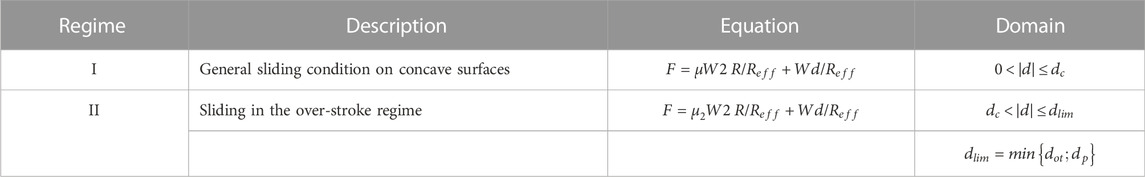
The backbone curve of the force-displacement relationship is shown in Figure 5. Compared with another recent study (Furinghetti et al., 2021b), the analytical formulation of the over-stroke stage of motion and the definition of the domain of application (Eqs 8, 17) are novel to this study.
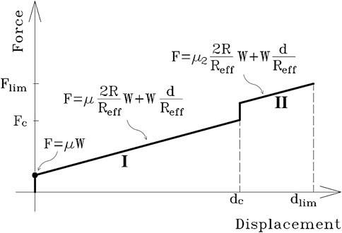
FIGURE 5. Force-displacement backbone curve for the over-stroke behaviour of the DCCSS bearing.
The proposed formulation has been compared with a few over-stroke tests described by Furinghetti et al. (2021b) in which a DCCSS specimen characterized by an effective radius of curvature of
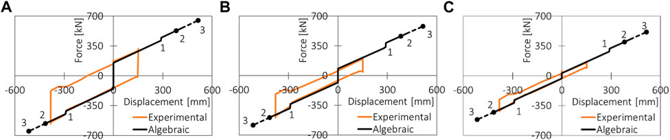
FIGURE 6. Force displacement test results from Furinghetti et al. (2021a) compared with the proposed analytical model for friction values: (A) 0.05; (B) 0.03; (C) 0.01.
3 Case study
A case study prototype structure was selected for the application of the proposed analytical model. The case study is representative of an existing building, designed according to the outdated İtalian seismic code (Decreto Ministreriale, 1986), with a low seismic design approach, retrofitted using the seismic isolation technique. The building, which is located in the city of L’Aquila (Iervolino et al., 2019), has a regular plan of approximately 240 m2 square meters and is characterized by a six-storey reinforced concrete (RC) frame structure (see Figure 7,B). The ground level height is 3.4 m, whereas all the other stories are 3.05 m in height. A staircase designed with knee beams is included, and slab thickness is 25 cm for all stories. Infill panels were considered to be regularly distributed in plan and elevation, with different opening percentages.
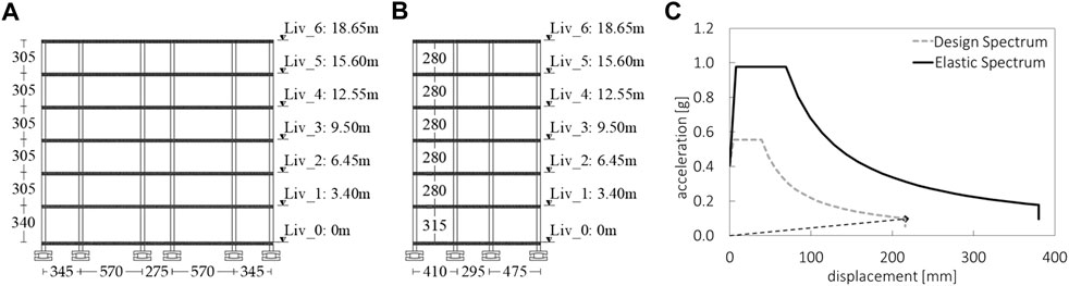
FIGURE 7. (A, B) Longitudinal (A) and transversal (B) sections of the case study. (C) ADRS design spectrum.
An isolation system composed of DCCSS bearings was designed for the collapse limit state (CLS), following the Italian seismic code (NTC 2018). The equivalent parameters are summarized in Table 2, where
TABLE 2. Main characteristics of the DCCSS for the case study.
Non-linear time history analyses were carried out to consider 20 different earthquakes (EQ) per three intensity measure levels characterized by return periods
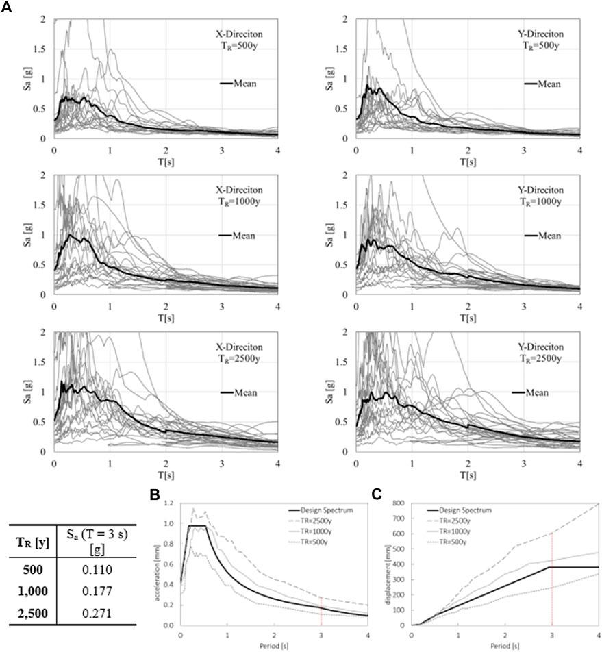
FIGURE 8. (A) Acceleration spectra for the 20 chosen records in X and Y directions for the selected return Periods
The comparison between the mean spectra at the different return period and the design spectrum is shown in Figure 8B and Figure 8C in terms of pseudo-acceleration and pseudo-displacement. Figure 8 also shows, for each return period, the mean value of the spectral acceleration Sa(T) corresponding to a vibration period of
3.1 Numerical model
A numerical simulation of the isolated building case study has been carried out using OpenSEES software (Mckenna et al., 2000) through non-linear dynamic analyses on a three-dimensional MdoF model.
For MDoF modelling (see Figure 9), the original fixed-based building model was upgraded by introducing a rigid grid at the base floor and seismic isolation devices below each column. The superstructure was modelled as a lumped plasticity model implemented at the end of beams and column elements. The flexural behaviour of the plastic hinges was modelled to take axial load interaction effects into account (Ibarra et al., 2005). The model included staircase knee beams and cantilever steps modelled as non-linear elements. A modified version of the model defined by Decanini et al. (2014) was used for masonry infill panels modelled with an equivalent compression-only strut taking into consideration a proper reduction of strength and lateral stiffness due to the influence of openings and potential premature out-of-plane collapse. In this study, 5% Rayleigh damping was used to model the viscous damping of the superstructure as a traditional reinforced concrete fixed-base building. More details regarding the superstructure modelling are provided by Ricci et al. (2018).
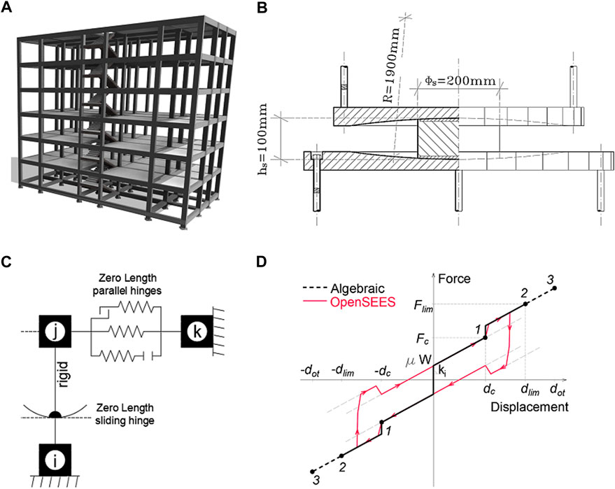
FIGURE 9. (A,B) Proposed case study structure (A) and DCCSS isolator (B). (C) Representation of the isolator numerical model. (D) Sloping dog bone shape constitutive law.
To describe the over-stroke behaviour of the DCCSS bearing, the SingleFPBearing element (Mckenna et al., 2000), providing a fixed bottom node (i-node) and a top node (j-node), was modified by adding three zero-length parallel hinges between the j-node and an external fixed node (k-node in Figure 9), as already discussed in other studies (Di Cesare et al., 2019, 2021; Ponzo et al., 2020; Ponzo et al., 2021; Cardone et al., 2022). In Figure 9 the resulting sloping dog bone shape for the constitutive law is shown with the main characterizing parameters, such as capacity displacement
3.2 Summary of results
Figure 10 shows the comparison between the proposed algebraic solution (see Eq 8, 17) and results of non-linear dynamic analyses for records that reached the limit displacement
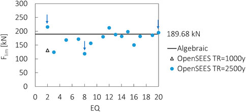
FIGURE 10. Isolation bearing limit shear forces
The
The black continuous line represents the algebraic solution for the bearing force
More detailed insight into the results of the analyses are provided in Figures 11–13, which shows the comparison between the algebraic solution and the MDoF model forces vs. displacement behaviour of a DCCSS bearing located in the central position, taking into account three example earthquakes for each return period (EQ2, EQ8, and EQ20 (indicated in Figure 10.
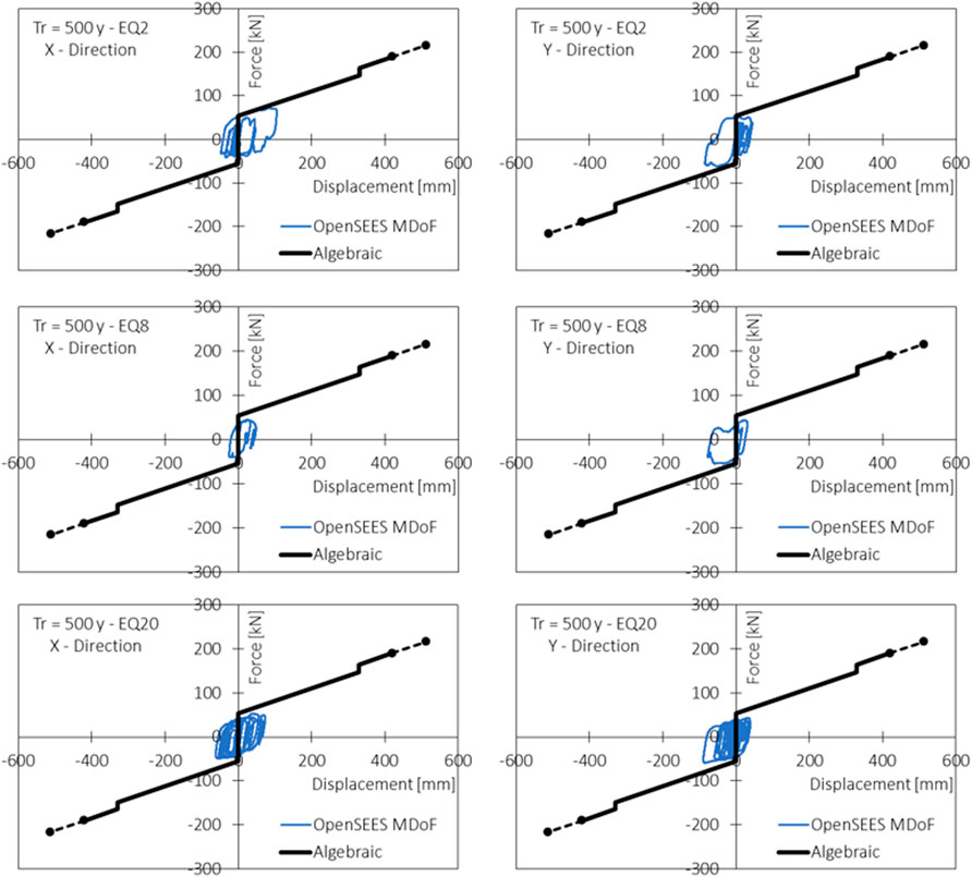
FIGURE 11. Single DCCSS bearing force vs. displacement relationship in X and Y directions for three example earthquakes (EQ2; EQ8; EQ20 for a return p oferiod 500 years.
Intensities corresponding to the design force (CLS,
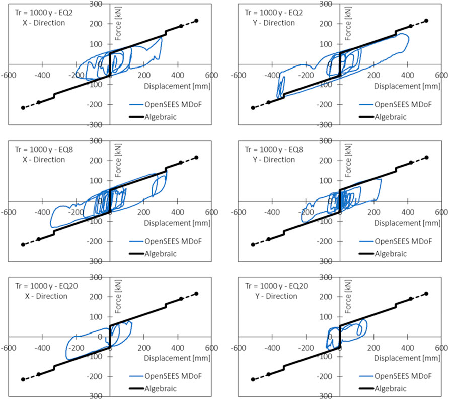
FIGURE 12. Single DCCSS bearing force vs. displacement relationship in X and Y directions for three example earthquakes (EQ2; EQ8; EQ20 for a return period of 1,000 years.
Some differences between the numerical and algebraic results can be observed for high seismic intensities (
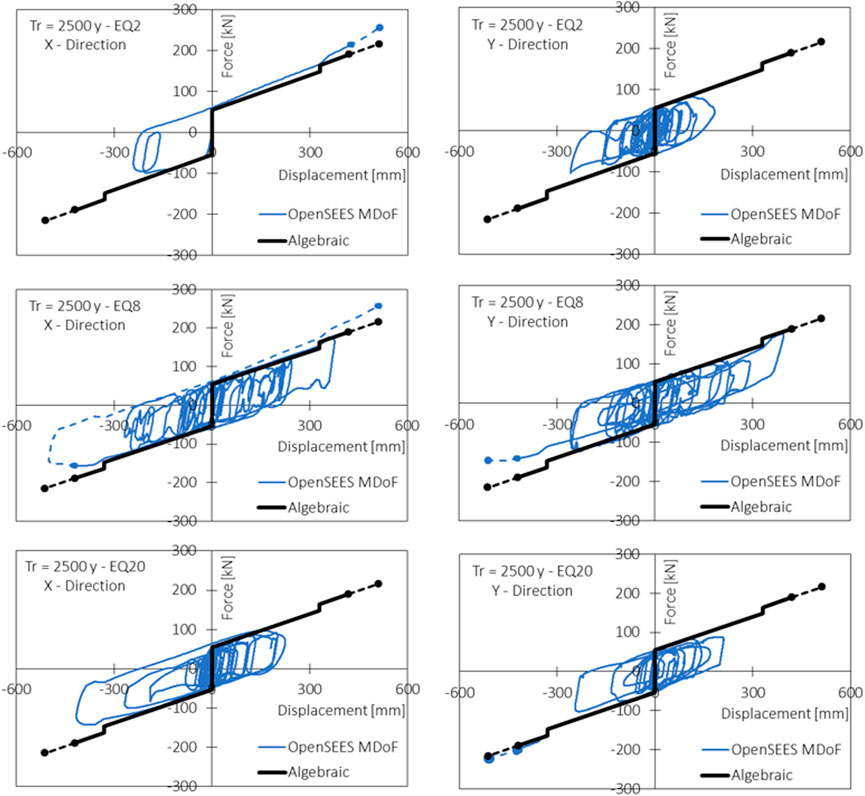
FIGURE 13. Single DCCSS bearing force vs. displacement relationship in X and Y directions for three example earthquakes (EQ2; EQ8; EQ20 for a return period of 2,500 years.
4 Conclusion
Starting with the formulations of past theories, this paper presents an extension of the DCCSS bearing force-displacement relationship to describe over-stroke behaviour in the simplified case of a DCCSS with an equal radii of curvature and equal friction coefficients for both concave plates.
The proposed algebraic solution is capable of representing forces that act on the isolation device for displacements higher than the geometric housing plate capacity, and is capable of identifying the displacements that correspond with the attainment of real limit conditions.
The proposed formulation has been provided to describe the sloping dog bone shape constitutive law estimated through experimental tests of the over-stroke regime when the rigid slider of the DCCSS bearing runs on the edge of the housing plates, exceeding its geometric capacity displacement. The algebraic solution for two failure mechanisms, which accounts for the rigid slider overturning kinematic and maximum contact pressure on the sliding interface, has been provided in terms of algebraic equations for the force-displacement relationships. The solution is valid for DCCSS bearings with a rigid slider and flat rim, equal radii of curvature, and friction coefficients on both of the concave plates.
The utility of the proposed solution is in checking the validity of numerical solutions of more complex models, and in designing the actual limit displacement and maximum shear force of the device with high accuracy. Furthermore, the maximum shear force
To validate the application of the proposed solution, non-linear dynamic analyses were implemented in OpenSees software to represent the case study of a six-storey RC frame building seismically isolated at the ground level with DCCSS bearings with over-stroke capacity. A three-dimensional MDoF model of the superstructure was upgraded with base isolation, implementing a multivariable friction model for the over-stroke displacement of DCCSS bearings, which also accounts for the effects of velocity and axial load variabilities. Additionally, structural analyses at intensity levels around design one have been carried out.
The results obtained by non-linear analysis strongly concurred with the results from the direct implementation of the proposed algebraic equations derived from the static condition. In particular, the proposed algebraic solution very accurately represented the shear forces acting on the single DCCSS bearing in the over-stroke regime. Furthermore, the results showed how the high accelerogram variability significantly affects the structural response. The proposed algebraic solution accounting for the over-stroke behaviour of DCCSS isolators should provide a safer tool for designers.
Further research should be carried out on the topic, and additional experimental testing campaigns are needed to evaluate possible dependencies of the over-stroke effect of DCCSS devices. The findings could help to facilitate highly accurate estimations of the seismic risk of seismically isolated structures with slider bearings, and develop appropriate safety factors in future building codes.
Data availability statement
The data analyzed in this study is subject to the following licenses/restrictions: The datasets analysed during the current study are available from the corresponding author on reasonable request. Requests to access these datasets should be directed to antonio.dicesare@unibas.it.
Author contributions
All authors contributed to the study conception and design. Material preparation, data collection, and analyses were performed by AD and AT. The first draft of the manuscript was written by AD and AT, and all authors read and approved the submitted manuscript.
Funding
This work was supported by RELUIS 2022–2024 project funded by the Italian Civil Protection Department.
Acknowledgments
The authors would like to acknowledge the financial support from the RELUIS 2022–2024 project WP 15, funded by the Italian Civil Protection Department, and FIP MEC srl (https://www.fipmec.it/) for providing support during the laboratory testing phase.
Conflict of interest
The authors declare that the research was conducted in the absence of any commercial or financial relationships that could be construed as a potential conflict of interest.
The reviewer MF declared a past co-authorship with the authors AC, FP to the handling editor.
Publisher’s note
All claims expressed in this article are solely those of the authors and do not necessarily represent those of their affiliated organizations, or those of the publisher, the editors and the reviewers. Any product that may be evaluated in this article, or claim that may be made by its manufacturer, is not guaranteed or endorsed by the publisher.
References
Almazán, J. L., and De La Llera, J. C. (2011). Analytical model of structures with frictional pendulum isolators. Earthq. Eng. Struct. Dyn. 31, 305–332.
Almazán, J. L., De La Llera, J. C., and Inaudi, J. A. (1998). Modelling aspects of structures isolated with the friction pendulum system. Earthq. Eng. Struct. Dyn. 27, 845–867.
Bao, Y., Becker, T. C., and Hamaguchi, H. (2017). Failure of double friction pendulum bearings under pulse-type motions. Earthq. Eng. Struct. Dyn. 46 (5), 715. doi:10.1002/eqe.2827
Becker, T. C., and Mahin, S. A. (2012). Correct treatment of rotation of sliding surfaces in a kinematic model of the triple friction pendulum bearing. Earthq. Engng. Struct. Dyn. 42, 311–317. doi:10.1002/eqe.2199
Becker, T. C., and Mahin, S. A. (2012). Experimental and analytical study of the Bi-directional behavior of the triple friction pendulum isolator. Earthq. Eng. Struct. Dyn. 41, 355–373. doi:10.1002/eqe.1133
Belfiore, N. P., Di Benedetto, A., and Pennestrì, E. (2000). Foundations of mechanics applied to machines. Milano, Italy: Casa Editrice Ambrosiana, 153–194. In Italian.
Bianco, V., Monti, G., and Belfiore, N. P. (2020). Fine-tuning of modelling strategy to simulate thermo-mechanical behavior of double friction pendulum seismic isolators. Ned. Univ. J. Res. 3, 165–172. doi:10.35453/NEDJR-STMECH-2019-0058
Bianco, V., Monti, G., Belfiore, N. P., and Vailati, M. (2021). Multibody kinematics of the double concave curved surface sliders: From supposed compliant sliding to suspected stick-slip. Pract. Period. Struct. Des. Constr. 26 (3), 04021024. doi:10.1061/(asce)sc.1943-5576.0000581
Cardone, D., Viggiani, L. R. S., Perrone, G., Telesca, A., Di Cesare, A., Ponzo, F. C., et al. (2022). Modelling and seismic response analysis of existing Italian residential RC buildings retrofitted by seismic isolation. J. Earthq. Eng., 1–25. doi:10.1080/13632469.2022.2036271
Constantinou, M. C., Mokha, A., and Reinhorn, A. (1990). Teflon bearings in base isolation, II: Modeling. J. Struct. Eng. (N. Y. N. Y). 116, 455–474. doi:10.1061/(asce)0733-9445(1990)116:2(455)
De Domenico, D., Ricciardi, G., and Benzoni, G. (2018). Analytical and finite element investigation on the thermo-mechanical coupled response of friction isolators under bidirectional excitation. Soil Dyn. Earthq. Eng. 106, 131–147. doi:10.1016/j.soildyn.2017.12.019
De Domenico, D., Ricciardi, G., Infanti, S., and Benzoni, G. (2019). Frictional heating in double curved surface sliders and its effects on the hysteretic behavior: An experimental study. Front. Built Environ. 5. doi:10.3389/fbuil.2019.00074
Decanini, L. D., Liberatore, L., and Mollaioli, F. (2014). Strength and stiffness reduction factors for infilled frames with openings. Earthq. Eng. Eng. Vib. 13, 437–454. doi:10.1007/s11803-014-0254-9
Decreto Ministreriale (1986). Norme Tecniche relative alle costruzioni sismiche, Decreto ministeriale del 24 gennaio 1986. Rome, Italy: Ministero delle Infrastrutture e dei Trasporti.
Di Cesare, A., Ponzo, F. C., and Telesca, A. (2021). Improving the earthquake resilience of isolated buildings with double concave curved surface sliders. Eng. Struct. 228 (111498), 111498. ISSN 0141-0296. doi:10.1016/j.engstruct.2020.111498
Di Cesare, A., Ponzo, F. C., Telesca, A., Nigro, D., Castellano, G., Infanti, S., et al. (2019). Modelling of the over stroke displacement of curved surface sliders using OpenSEES. Hong Kong: OpenSEES Days Eurasia.
Fenz, D. M., and Constantinou, M. C. (2006). Behaviour of the double concave Friction Pendulum bearing. Earthq. Eng. Struct. Dyn. 35, 1403–1424. doi:10.1002/eqe.589
Fenz, D. M., and Constantinou, M. C. (2008). Report No. MCEER-08-0007. Buffalo, NY: Multidisciplinary Center for Earthquake Engineering Research.Mechanical behavior of multi-spherical sliding bearings
Fenz, D. M., and Constantinou, M. C. (2008). Spherical sliding isolation bearings with adaptive behavior: Experimental verification. Earthq. Eng. Struct. Dyn. 37, 185–205. doi:10.1002/eqe.750
Furinghetti, M., Lanese, I., and Pavese, A. (2020). Experimental assessment of the seismic response of a base-isolated building through a hybrid simulation technique. Front. Built Environ. 6. doi:10.3389/fbuil.2020.00033
Furinghetti, M., and Pavese, A. (2021b) Modeling strategies for the lateral response of curved surface slider devices under extreme displacement demands. Proceedings of the COMPDYN 2021, 8th ECCOMAS Thematic Conference on Computational Methods in Structural Dynamics and Earthquake Engineering, June 2021, Streamed from Athens, Greece.
Furinghetti, M., Yang, T., Calvi, P. M., and Pavese, A. (2021a). Experimental evaluation of extra-stroke displacement capacity for Curved Surface Slider devices. Soil Dyn. Earthq. Eng. 146, 106752. doi:10.1016/j.soildyn.2021.106752
Ibarra, L. F., Medina, R. A., and Krawinkler, H. (2005). Hysteretic models that incorporate strength and stiffness deterioration. Earthq. Eng. Struct. Dyn. 34, 1489–1511. doi:10.1002/eqe.495
Iervolino, I., Chioccarelli, E., and Convertito, V. (2011). Engineering design earthquakes from multimodal hazard disaggregation. Soil Dyn. Earthq. Eng. 31, 1212–1231. doi:10.1016/j.soildyn.2011.05.001
Iervolino, I., Spillatura, A., and Bazzurro, P. (2019) RINTC-E project: Towards the assessment of the seismic risk of existing buildings in Italy. Proceedings of the 7th International conference on computational methods in structural dynamics and earthquake engineering – COMPDYN 2019, June 2019, Crete, Greece.
Iervolino, I., Spillatura, A., and Bazzurro, P. (2018). Seismic reliability of code-conforming Italian buildings. J. Earthq. Eng. 22 (2), 5–27. doi:10.1080/13632469.2018.1540372
Lomiento, G., Bonessio, N., and Benzoni, G. (2013). Friction model for sliding bearings under seismic excitation. J. Earthq. Eng. 17, 1162–1191. doi:10.1080/13632469.2013.814611
Mazza, F., Mazza, M., and Vulcano, A. (2017). Nonlinear response of rc framed buildings retrofitted by different base-isolation systems under horizontal and vertical components of near-fault earthquakes. Earthquakes Struct. 12 (1), 135–144. doi:10.12989/eas.2017.12.1.135
Mckenna, F., Fenves, G. L., Scott, M. H., and Jeremic, B. (2000). Open system for earthquake engineering simulation (OpenSEES). Berkeley (CA): PEER Center, University of California.
Mostaghel, N., and Davis, T. (1997). Representations of Coulomb friction for dynamic analysis. Earthq. Eng. Struct. Dyn. 26 (5), 541–548. doi:10.1002/(sici)1096-9845(199705)26:5<541::aid-eqe660>3.0.co;2-w
Nikravesh, P. E. (2018). Planar multibody dynamics-formulation, programming with , and applications. New York, NY, USA: CRC Press, Taylor & Francis Group, 355–382.
NTC (2018). Norme Tecniche per le Costruzioni, Decreto ministeriale del 17 gennaio 2018. Rome, Italy: Ministero delle Infrastrutture e dei Trasporti.
Pavese, A., Furinghetti, M., and Casarotti, C. (2018). Experimental assessment of the cyclic response of friction-based isolators under bidirectional motions. Soil Dyn. Earthq. Eng. 114, 1–11. doi:10.1016/j.soildyn.2018.06.031
Pigouni, E. A., Castellano, M. G., Infanti, S., and Colato, G. P. (2019). Full-scale dynamic testing of pendulum isolators (Curved surface sliders). Soil Dyn. Earthq. Eng. 130, 105983. doi:10.1016/j.soildyn.2019.105983
Ponzo, F. C., Di Cesare, A., Telesca, A., Nigro, D., Castellano, M. G., and Infanti, S. (2020) Influence of DCCSS Bearings Over-Stroke and breakaway on the seismic response of isolated buildings. Proceedings of the 17th World Conference on Earthquake Engineering, September 2020, Sendai, Japan.
Ponzo, F. C., Di Cesare, A., Telesca, A., Pavese, A., and Furinghetti, M. (2021) Advanced modelling and risk analysis of RC buildings with sliding isolation systems designed by the Italian seismic code. Appl. Sci. (Basel)., 11, 1938, doi:10.3390/app11041938
Ponzo, F. C., Di Cesare, A., Leccese, G., and Nigro, D. (2017). Shake table testing on restoring capability of double concave friction pendulum seismic isolation systems. Earthq. Eng. Struct. Dyn. 46, 2337–2353. doi:10.1002/eqe.2907
Ponzo, F. C., Di Cesare, A., Leccese, G., and Nigro, D. (2019). Standard requirements for the recentering capability of curved surface sliders. Ing. Sismica 36, 95–106.
Popov, V. (2010). Contact mechanics and friction-physical principles and applications. Berlin, Germany: Springer, 175–230.
Quaglini, V., Dubini, P., and Poggi, C. (2012) Experimental assessment of sliding materials for seismic isolation systems. Bull. Earthq. Eng., 10, 717, doi:10.1007/s10518-011-9308-9
Quaglini, V., Gandelli, E., and Dubini, P. (2019). Numerical investigation of curved surface sliders under bidirectional orbits. Ing. Sismica 36, 118–136.
Ricci, P., Manfredi, V., Noto, F., Terrenzi, M., Petrone, C., Celano, F., et al. (2018). Modeling and seismic response analysis of Italian code-conforming reinforced concrete buildings. J. Earthq. Eng. 22, 105–139. doi:10.1080/13632469.2018.1527733
Sarlis, A. A., and Constantinou, M. C. (2016). A model of triple friction pendulum bearing for general geometric and frictional parameters. Earthq. Eng. Struct. Dyn. 45, 1837–1853. doi:10.1002/eqe.2738
Sarlis, A. A., and Constantinou, M. C. (2013). “Model of triple friction pendulum bearing for general geometric and frictional parameters and for uplift conditions,” Report No. MCEER-13-0010 (Buffalo, NY: Multidisciplinary Center for Earthquake Engineering Research).
Tsai, C. S., Chiang, T. C., and Chen, B. J. (2005). Experimental evaluation of piecewise exact solution for predicting seismic responses of spherical sliding type isolated structures. Earthq. Eng. Struct. Dyn. 34 (9), 1027–1046. doi:10.1002/eqe.430
Keywords: base isolation, double concave curved surface slider, over-stroke displacement, mechanical modelling, experimental tests, non-linear dynamic analysis
Citation: Di Cesare A, Ponzo FC and Telesca A (2022) Mechanical model of the over-stroke displacement behaviour for double concave surface slider anti-seismic devices. Front. Built Environ. 8:1083266. doi: 10.3389/fbuil.2022.1083266
Received: 28 October 2022; Accepted: 10 November 2022;
Published: 12 December 2022.
Edited by:
Dario De Domenico, University of Messina, ItalyReviewed by:
Emanuele Gandelli, University of Brescia, ItalyMarco Furinghetti, University of Pavia, Italy
Zhipeng Zhao, Tohoku University, Japan
Copyright © 2022 Di Cesare, Ponzo and Telesca. This is an open-access article distributed under the terms of the Creative Commons Attribution License (CC BY). The use, distribution or reproduction in other forums is permitted, provided the original author(s) and the copyright owner(s) are credited and that the original publication in this journal is cited, in accordance with accepted academic practice. No use, distribution or reproduction is permitted which does not comply with these terms.
*Correspondence: Antonio Di Cesare, antonio.dicesare@unibas.it